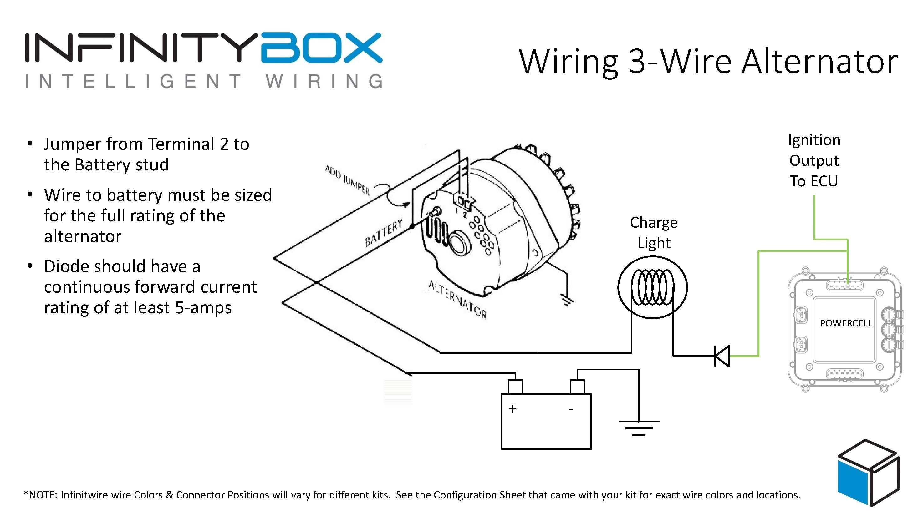

With a basic understanding of the diagram, you can make the necessary repairs or replacements when they are needed. This diagram can help you understand how the different components of the alternator are connected and how they function together in order to keep the vehicle running smoothly. Understanding a 3-wire alternator wiring diagram is essential for anyone who is working on an automotive project. This harness is also connected to the voltage regulator, which is used to regulate the voltage output of the alternator. This includes the headlights, dashboard lights, and other accessories. This wiring harness is used to provide power to various components in the vehicle. The main wiring harness is connected to the alternator and the starter. This wire carries the current from the ignition switch to the alternator so that it can be used to start the engine. The alternator is also connected to the ignition switch through a yellow wire. This wire is used to regulate the voltage output of the alternator. The alternator is connected to the voltage regulator through a white wire. This black wire is used to provide power to the starter when the ignition is turned on. The battery is also connected to the starter through a black wire. This power is then used to charge the battery. The voltage at the fuse box and the ignition are monitored by the 3-wire.
#Subur 3 wire alternator wiring diagram upgrade
It is an upgrade over the 1-wire variety and may be installed in earlier vehicles. The red wire is used to provide power to the alternator when the engine is running. Most people refer to a standard General Motors alternator with an integrated regulator as a 3-wire alternator, often known as a 3-pin alternator. The battery is connected to the alternator through a red wire. Each of these components is connected in a specific way to ensure that the alternator works correctly. The regulator section consists of the voltage regulator, ignition switch, and the main wiring harness. The power section consists of the battery, alternator, and starter. The 3-wire alternator wiring diagram can be divided into two sections: the power section and the regulator section. It is important to understand the diagram so that you can make the necessary repairs or replacements when they are needed. They can help you understand how the components of your alternator are connected and how they function together. Web a 3 wire alternator wiring diagram has three wires: The wiring diagram is a tool used to understand the functions and relationships of the segments within a circuit. The ‘battery charging wire’ on the alternator shows that the positive side is connected to the battery.

In the automotive industry, 3-wire alternator wiring diagrams are often used as a reference. Review Of Subaru 3 Pin Alternator Wiring Diagram Online References. Understanding 3-Wire Alternator Wiring Diagrams


 0 kommentar(er)
